1. WiseUser needs full geometry information
While picking on cloud, it needs almost all geometry parameters. After creating a new project in WiseUser, setting the parameter header position and length is necessary
(unless the parameters are put according to the default definition). Otherwise, WiseUser may not read correctly the geometry.
As shown in Fig.1, all of 15 parameters, except the last one ("Scalar to all coordinates"), are necessary for WiseUser.
It is suggested that the user put geometry parameters as recommended in the table.
|
Item |
Parameter name |
Abbr. name |
Def. position |
Def. length |
Comment |
1 |
Original field record number |
ffid |
9 |
4 |
recommended by SEGY_rev_1 |
2 |
Trace number within the original field record |
channel |
13 |
4 |
recommended by SEGY_rev_1 |
3 |
Distance from the source to the group |
offset |
37 |
4 |
recommended by SEGY_rev_1 |
4 |
Receiver group elevation |
g_elev |
41 |
4 |
recommended by SEGY_rev_1 |
5 |
Source elevation |
s_elev |
45 |
4 |
recommended by SEGY_rev_1 |
6 |
Source depth |
s_depth |
49 |
4 |
recommended by SEGY_rev_1 |
7 |
Source coordinate - x |
source_x |
73 |
4 |
recommended by SEGY_rev_1 |
8 |
Source coordinate - y |
source_y |
77 |
4 |
recommended by SEGY_rev_1 |
9 |
Receiver group coordinate - x |
group_x |
81 |
4 |
recommended by SEGY_rev_1 |
10 |
Receiver group coordinate - y |
group_y |
85 |
4 |
recommended by SEGY_rev_1 |
11 |
Source line number |
s_line |
181 |
4 |
recommended by WiseUser |
12 |
Source station number |
s_stat |
185 |
4 |
recommended by WiseUser |
13 |
Receiver group line number |
g_line |
189 |
4 |
recommended by WiseUser |
14 |
Receiver group station number |
g_stat |
193 |
4 |
recommended by WiseUser |
15 |
Scalar to all coordinates |
scalar |
71 |
2 |
recommended by SEGY_rev_1 |
|
Fig.1 The parameters needed by WiseUser |
|
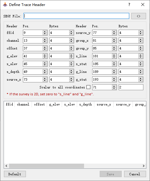
Fig.2 The dialog of "Define trace header" |
2. Dialog setting
After creating a new project, choose the menu“SEGY->Define trace header” to open the dialog as shown in Fig.2.
SEGY File
Click  to open a SEGY file, from which header parameters are read according to the definition on the upper table of the dialog(Fig.3). to open a SEGY file, from which header parameters are read according to the definition on the upper table of the dialog(Fig.3).
Header Pos.
Start byte in the trace header.
Bytes
Number of bytes occupied by a geometry parameter. It takes either 4 or 2. For example, the start byte for FFID is 9, and the number of bytes is 4, then the parameter occupys the header bytes 9-12.
Enable scalar
Unchecked by default. If checked the "scalar to coordinates" will be enabled (refer to "special trace header" in the following specification).

Reset all the settings (as in Fig.2).

Save the settings and exit.

Exit without saving the settings.
The header values
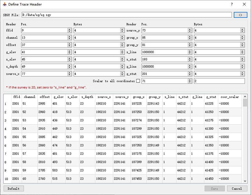
On the down part the header values in the first 100 traces of the SEGY file are displayed, as in Fig.3. It helps to check the settings (please refer to "Check the setting automatically").
|
|
Fig3. The header definition for the demo data "eg.sgy" |
3. Special trace header
Here we call 3 parameters as the special header. They are "source line number", "receiver group line number", and "scalar to all coordinates".
Source line number and receiver group line number
The length of trace header block is fixed, i.e., 240 bytes. So the start-byte takes generally a value between 1 and 240. But we allow these two position settings to take values
beyond this range as seen in Fig.3. There are two scenarios:
(1) In order to treat 2D as a specific case of 3D, we would fabricate the line number. Accordingly we set 0 for both positions of source line number and receiver group line number,
and the program will mandatorily use 1 as both of the parameters.
(2) For some 3D or wide-line surveys the line number and station number is combined into a header parameter. WiseUser needs to separate them from each other.
For example, as in Fig.3, the start position for the combination of the two source parameters is 193, and the length is "4 bytes". The setting value for the source line number is 1000,000,
which is bigger than 240 and it is automatically used as a divisor.
e.g.1: The value from the header bytes 193-196 is 1044212, we get the line number as 1 by divding 1000,000 and rounding the quotient. The remainder, 44212, is the source station number.
e.g.2: The value from the header bytes 201-204 is 3041225, we get 3 as the group line number and 41225 as the group station number.
scalar to all coordinates
Another special trace header is "scalar to all coordinates". It is generally stored in bytes 71-72 recommended by "SEGY_rev_1".
With the value we can convert a coordinate of integer value to floating-point one. So that the coordinate in the header can be more precise.
According to "SEGY_rev_1", if the scalar is positive it is used as a multiplier, otherwise, it is used as a divisor.
When the "scalar to all coordinates" is checked in the dialog box, the scalar will be enabled.
e.g.1: If the scalar from the header is -100 (minus 100), the coordinate value from the header is 20312350, then dividing it by 100, we get the real coordinate as "203123.50".
e.g.2: If the scalar from the header is 100 , the coordinate value from the header is 12350, then multipling it by 100, we get the real coordinate as "1235000".
|
4. Check the setting automatically
WiseUser assumes that the header parameter in SEGY file is correct. WiseUser will automatically check the correctness of the settings by evaluating the header values of the first 100 traces.
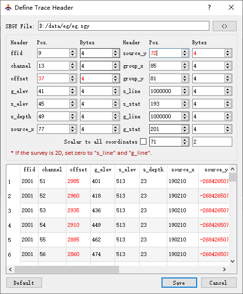
For instance, in the dialog box we intentionally set 72 other than 73 as the position value of source x coordinate, as a result, we get all minus values, obviously not correct, in the column of source x coordinate of the table.
WiseUser will display the probably wrong data in red for highlight (Fig.3).
The criteria for the evaluation are as follows:
FFID: positive.
Channel: positive, and less than 10,000,000.
Offset: absolute value is less than 100,000.
Elevation: absolute value is less than 10,000 meter.
Source depth: equal to or bigger than zero, but less than 300.
X coordinate: positive, and less than 1,000,000.
Y coordinate: positive, and less than 10,000,000.
Line number: positive.
Station number: positive.
Other logic criteria:
(1) The channel number must be different in one shot.
(2) All shot parameters must be the same in one shot.
(3) The source elevation has a different header position from the group elevation.
(4) The offsets cannot be the same in one shot.
|
|
Fig.4. Display the probably wrong header values in red |
|
Note: (1) In order to make the checking effective, the user has to open a SEGY file.
(2) The data in red suggest that the header definition may be not correct, or the geometry data themselves may be wrong. Even so the user still can store the definition.
|